Powering on and off speakers automatically with M5StickC and IR
I have a very particular issue for which I hadn’t found a solution until now. I use a regular set of speakers with my TV, basic but with everything I need (good sound, line in, optical in, bluetooth - which I don’t use but we all know everything is better with bluetooth). Now the problem is that although most TVs and streaming devices support controlling other devices (like set-top boxes or speaker systems) via different methods (e.g. HDMI or IR) my speakers have an IR remote, but are not common enough for the TVs to know the right codes. That means I need to use two remotes, and even worse, that I usually forget my speakers on.
Curiously enough, talking with my colleague Paul Sobek he had the exact same issue. Discussing it more we realized we could implement a rather simple solution: power a microcontroller with the TV’s USB, so whenever the TV is on the microcontroller would run and send the right codes to turn the speakers on. For the off case, a small battery with just enough power for the microncontroller to send the speaker off code and die would be enough.
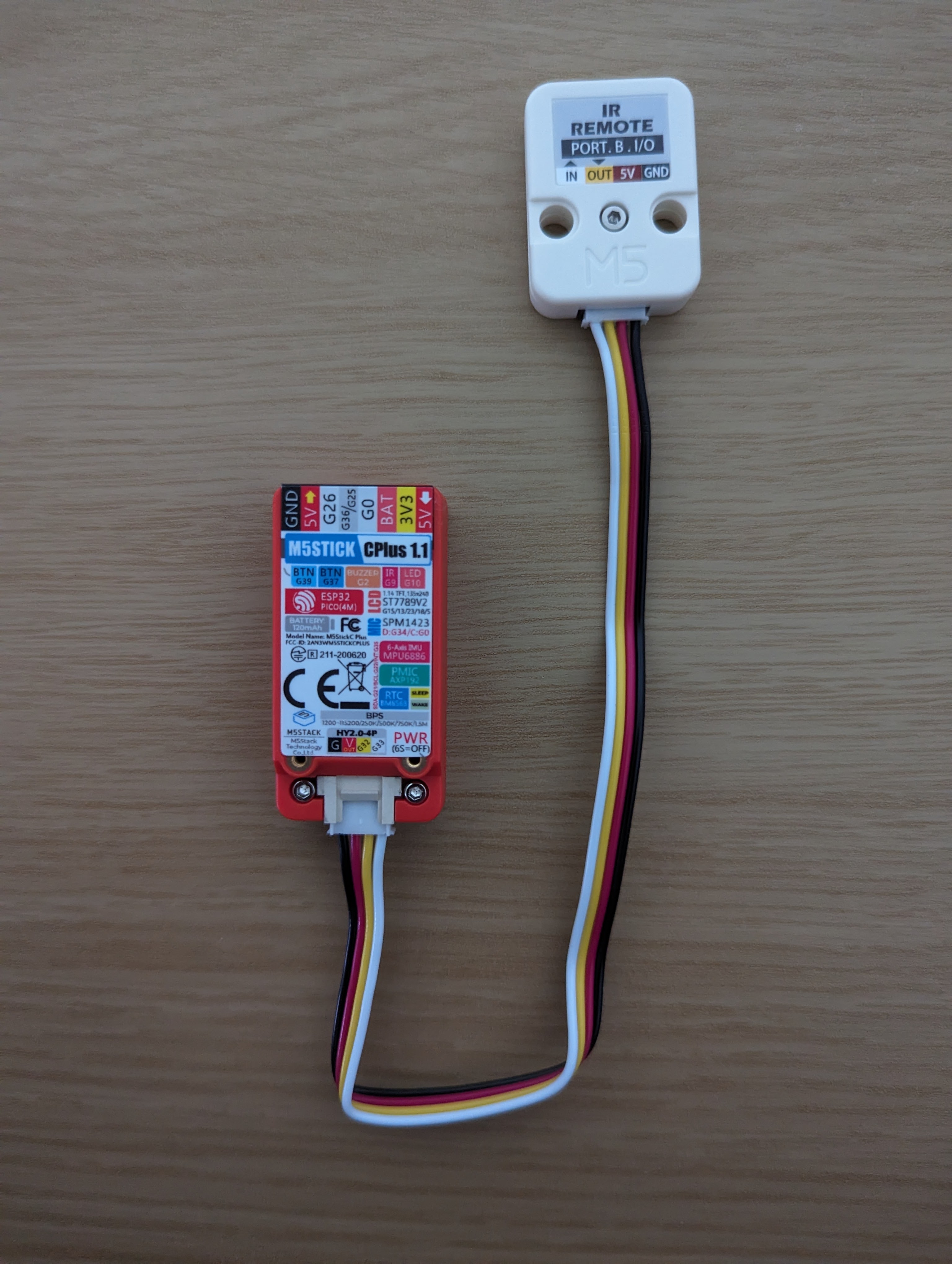
Looking for devices to implement it, he found the M5StickC PLUS, a very small device based on ESP32 and with the features we needed (USB, IR transmitter and battery) so we got a couple to test them. We also got an IR Unit for it as we needed a way to copy the codes from the speakers remote (and it would also be useful for future expansion).
Environment Setup
First step is to get everything set up to start coding. As I want to get a prototype up and running the fastest possible I’ll be using the Arduino IDE for now. Even with that the M5StickC is not that straightforward, a support package needs to be added manually. You can find the instructions in the official documentation.
After everything is installed, open the Hello World example from
File > Examples > M5StickCPlus > Basics, select the M5Stick-C-Plus board in
Tools > Board > M5Stack and click upload. A “Hello World” on the M5Stick screen means we are
ready.
First IR Program
Now is time to test the IR unit. First we need to connect everything, the IR Unit includes the Grove cable, and connectors go in only one way so that’s easy enough.
Then we try the example from File > Examples > M5StickCPlus > Unit > IR. The screen now shows
“Test for IR receiver:”. Doing the tests suggested in the example comments I can see the infrared
light from the emitter with my phone camera, and I get a “detected” on the display when I press a
button from my remote control (although I also get some random “detected” messages without doing)
anything.
Analyzing a bit more the example code, we see that it’s just using digitalWrite (for the emitter)
and digitalRead for the receiver. That just emits and detects IR light, but it doesn’t really
tell us anything about the codes we need nor lets us send them, so it’s not very useful.
Working with IR Codes
Searching for a way to work with actual IR codes (and not just “light”), we find this guide:
Night Lamp with Atom Lite, Neopixel Strip and IR Remote
which uses a library called IRRemoteESP8266.
This library can be installed directly from the Arduino IDE through the
Sketch -> Include Library -> Manage Libraries... menu, searching for “IRremoteESP8266” and
selecting Install.
With that we can now find the library examples in the Examples menu. Starting with
IRRemoteESP8266 > IRrecvDemo, we adjust it to the M5StickC Plus configuration replacing
// Note: GPIO 16 won't work on the ESP8266 as it does not have interrupts.
// Note: GPIO 14 won't work on the ESP32-C3 as it causes the board to reboot.
#ifdef ARDUINO_ESP32C3_DEV
const uint16_t kRecvPin = 10;  // 14 on a ESP32-C3 causes a boot loop.
#else  // ARDUINO_ESP32C3_DEV
const uint16_t kRecvPin = 14;
#endif  // ARDUINO_ESP32C3_DEV
with the right receiver pin:
const uint16_t kRecvPin = 33;
Running the program and starting pressing buttons in our remote control, we can see the different
codes being decoded in the Serial Monitor. For example in my case 8E7629D is the code for the
power button. You’ll also notice that a press and hold will be decoded as the button code followed
by repeated FFFFFFFFFFFFFFFF. The codes you get might differ (for example in length) depending on
the encoding your remote uses. Note down a relevant code from your remote for the next step.
Moving on to the IRRemoteESP8266 > IRsendDemo, we know need to change
const uint16_t kIrLed = 4; // ESP8266 GPIO pin to use. Recommended: 4 (D2).
with the right emitter port:
const uint16_t kIrLed = 32; // ESP8266 GPIO pin to use. Recommended: 4 (D2).
And, assuming your remote uses NEC encoding, the code in the
irsend.sendNEC(0x00FFE01FUL);
line with the one we captured in the previous step. In my case it ends up like:
irsend.sendNEC(0x008E7629D);
Finally, the example also tries other encodings. You can either leave them there (they’ll like
won’t do anything) or remove them (in case they trigger any device you may have). In my case I’m
just leaving the sendNec instruction, but increasing the delay so I can notice the effect.
We now run the example and point the IR emitter to the device we are controlling, and check if it has the effect of the button we captured previosuly. I can see my speakers turn off and on, meaning everything is working as expected.
Building an IR cloner
We will now combine both examples to build an IR cloner. The idea is that you press a button in the M5Stick to enter “record mode”, press the remote button you want to clone, save the new code in the M5Stick. From there by pressing another button in the M5Stick you will send the same code. I’ll be using button B (small one) to enter programming mode, and button A (big one) to confirm and send the code.
You can find the code for this step in
ir_cloner.ino. You’ll
note that most of the code is just to draw the instructions on the screen, but that’s not very
relevant for this post. The important bits are the loop() function and the while loop inside
the program_mode() function.
Adding persistence
Now this looks good, but having it to program every time is not convenient, and won’t help us with our goal. So in this step will save and load the IR code from the EEPROM to persist it across power cycles.
The needed changes are in this commit and you can find the resulting code in persistent_ir_cloner.ino.
Following TV power
As the last step we need to make the device follow the TV power state, that means sending the IR
code every time the TV turns on or off. For that I’ll be using the PMIC’s library,
AXP192. To learn more about it, you can
also check the M5StickCPlus > Basics > AXP192 example.
For our case, just checking if there’s
power in the USB with M5.Axp.GetVBusVoltage() should be enough. We can wait for USB power to
drop, send the code to turn off the speakers and turn off the M5Stick. Once the TV turns back on
power on the USB will automatically power on the device and trigger a code again.
You can find the changes in this commit and the resulting code in ir_tv_follower.ino. You’ll notice that in my final code I switched to pin 9 for the IR emitter, this is so I can use the M5Stick integrated one to control the speakers, and disconnect or repurpose the external IR unit.
What’s next
There are many improvements that can be made, for example improving the power detection logic, adding support for more buttons, detecting if the speakers are on or off, but those may be topics for a different post.