Arduino & Raspberry Pi talking wirelessly [Part 1]
In this guide I'll be explaining how to communicate an Arduino and a Raspberry Pi with nRF24L01+ modules. I found many guides to accomplish this around the Internet, but none of them was complete or fully worked for me, so I decided to log what I've done for future reference. Part 1 has an introduction and an explanation of how to prepare the Arduino, while in the second part I'll prepare the Raspberry Pi and test everything.
nRF24L01+
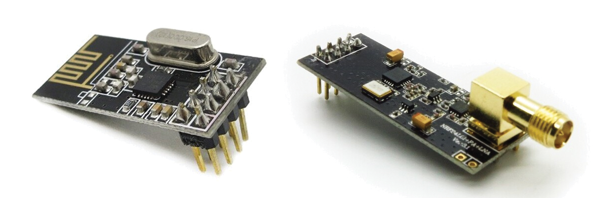
The modules I'll be using are, as I mentioned, based on the nRF24L01+ chip from Nordic Semiconductors. The reason to choose them over other alternatives is that while being cheap they do have many useful features not found on the cheapest modules, such as many pipelines, buffers and auto-retransmit. In this case one of the modules is a normal one (the one in the left), while the other has LNA and PA (Low noise amplifier and Power amplifier) circuits for improved range (the one in the right). Both are from Itead Studio.
SPI background
To interact with these modules we have to use the SPI bus. SPI is a serial interface as the name suggets (Serial Peripheral Interface) which works in a master/slave setup. The SPI bus can operate with a single master device and one or more slave devices. It uses three common wires and one extra wire per slave device. The three common wires (connected to all the devices) are:
- SCK: serial clock (output from master)
- MOSI: master output - slave input (output from master)
- MISO: master input - slave output (output from slave)
The extra wire is called SS (slave select) or CS (chip select) and its function is to enable the slave device we want to talk (only one slave can be enabled at the same time). If you want to know more about SPI and how it works you can always go to Wikipedia. In this case we'll be using only one slave, but a you can see a common layout with multiple slaves in the following picture.
![Typical SPI bus: master and three independent slaves. [Wikipedia]](/assets/363px-SPI_three_slaves.svg_.png)
We'll begin preparing the Arduino because it's the easieast part. This instructions are for the Arduino ADK (they also work with the Arduino Mega 2560). You can use any Arduino, but keep it mind that the connections usually vary. If you search your Arduino model on the web you will find which pins you have to use for SPI. In the following table you will find the needed connections.
|
nRF24L01+ Pin |
Line |
Arduino Pin |
Wire Color (Just for reference) |
|
1 |
GND |
GND |
Black |
|
2 |
3V3 |
3V3 |
Red |
|
3 |
CE |
9 |
Yellow |
|
4 |
CSN (SPI) |
10 |
Blue |
|
5 |
SCK (SPI) |
52 (SCK) |
Brown |
|
6 |
MOSI (SPI) |
51 (MOSI) |
Green |
|
7 |
MISO (SPI) |
50 (MISO) |
White |
|
8 |
Interrupt |
- |
- |
You should notice a few things:
- The module works with 3.3V, so you have to connected to that line and NOT to the 5V line
- The module uses an extra "data" wire besides the SPI ones (CE: Chip Enable)
- The library doesn't use the SS Arduino pin, but a regular digital pin as SS
- Both of this connections (CE and SS) are defined when initializing the library and can be changed
- The SCK, MOSI and MISO connections are the "Arduino dependant" and we'll be in another pins if you're using a different Arduino
- The module's 8th pin is for interrupts and it's not currently used by the library
I made an image in Fritzing in case it is easier for you to see the connections graphically:
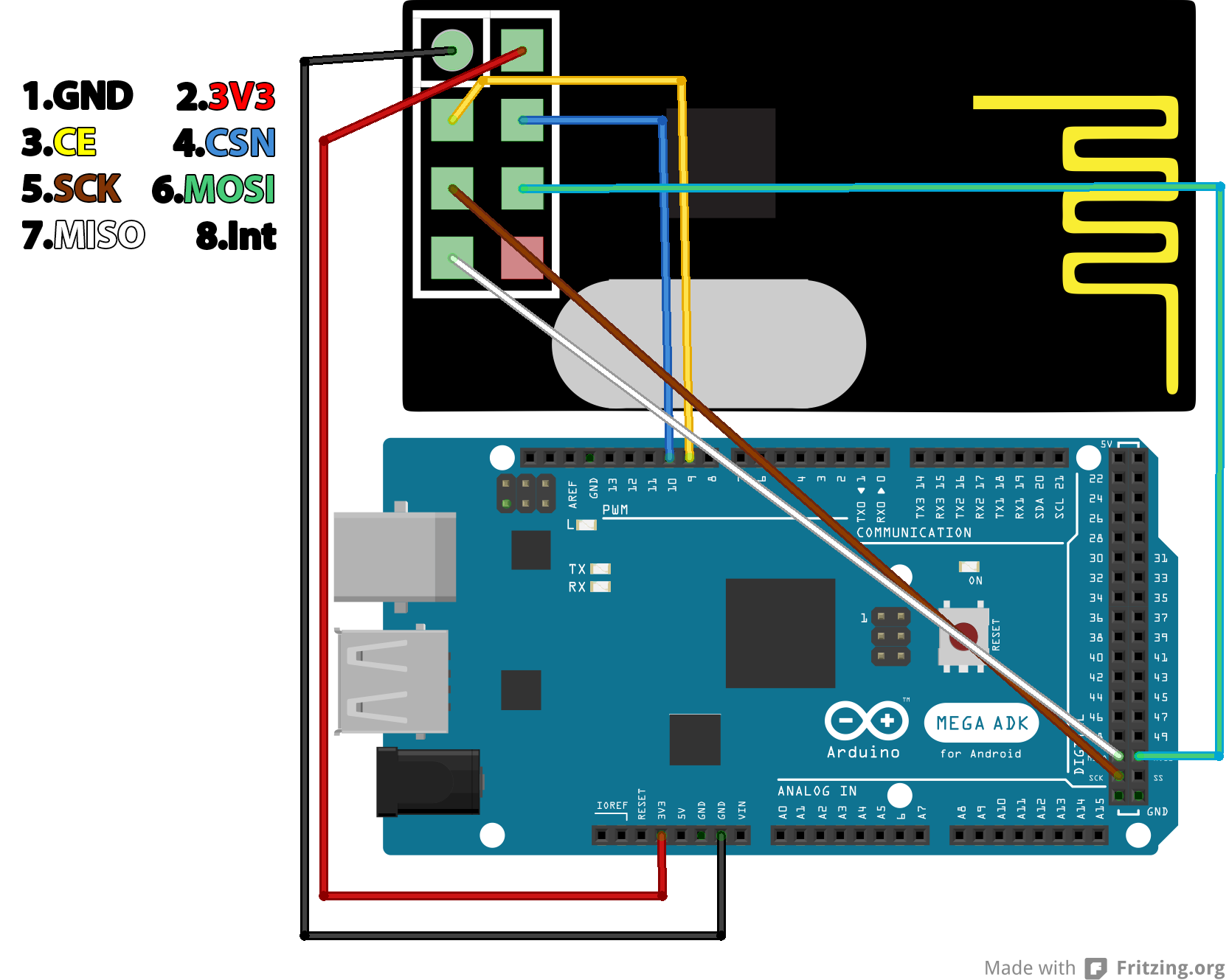
If you plan to use a breadboard you will need to make an adapter (if you have a common breadboard, there's no way to put the module directly without shorting its pins)
Programming stage
So everything it's ready and it's time to program the Arduino. There are many libraries to use this modules, the one I used it's RF24 from maniacbug. If you explore the network of this repository you will find there're a lot of forks, but I couldn't find any relevant difference (not that I spent much time searching). As any Arduino library, just clone the repo from Github or download the zip file and install it. If like me, you downloaded the zip version of the Arduino IDE, just unzip the RF24-master folder (the one inside the zip, not the zip itself) in the "libraries" folder from your IDE and rename to RF24. In any other case, or if that doesn't work, here are more detailed instructions.
So everything is ready, just open your Arduino IDE and go to File > Examples > RF24 > pingpair and load it to your Arduino. If you read a little the sketch, you will have noticed that the pin 7 will control the role of the Arduino. If it is left disconnected the Arduino enters the "pong back" role, in which it'll wait for a message and send it back when received. If the pin is connected to ground, the Arduino will enter the "ping out" role, in which it'll constantly send packets and wait for their confirmation. Keep in mind that the Arduino won't change the role while running, you will have to reset it if you change the pin state.
So everything is ready and it's time to program the Arduino. When I first wrote this post I used the RF24 library from maniacbug but it hasn't been updated for a few years so I'll be using a more updated fork from TMRh20, which can be found in GitHub. As of today the library can be installed directly from the Arduino IDE. Just go to Sketch > Include library > Manage Libraries..., search for RF24 and install it.
Next we'll check if the communication with the module works ok (the SPI bus, not the RF communication with another module). To do it we'll use the Getting Started example from the library with some modifications. Open it (File > Examples > RF24 > GettingStarted) and then (a) add
#include <printf.h>
on the includes block;
(b) change
/* Hardware configuration: Set up nRF24L01 radio on SPI bus plus pins 7 & 8 */
RF24 radio(7,8);
for
/* Hardware configuration: Set up nRF24L01 radio on SPI bus plus pins 7 & 8 */
RF24 radio(9,10);
(c) add
printf_begin();
after Serial.begin(115200); on the setup method;
(d) and add
radio.printDetails();
just before
// Start the radio listening for data
radio.startListening();
at the end of the setup method.
Upload the code and open the Serial Monitor on the Arduino IDE (or any serial terminal you like) and set it to 115200 bauds. You should get something like this:
RF24/examples/GettingStarted
*** PRESS 'T' to begin transmitting to the other node
STATUS = 0x0e RX_DR=0 TX_DS=0 MAX_RT=0 RX_P_NO=7 TX_FULL=0
RX_ADDR_P0-1 = 0x65646f4e31 0x65646f4e32
RX_ADDR_P2-5 = 0xc3 0xc4 0xc5 0xc6
TX_ADDR = 0x65646f4e31
RX_PW_P0-6 = 0x20 0x20 0x00 0x00 0x00 0x00
EN_AA = 0x3f
EN_RXADDR = 0x02
RF_CH = 0x4c
RF_SETUP = 0x03
CONFIG = 0x0e
DYNPD/FEATURE = 0x00 0x00
Data Rate = 1MBPS
Model = nRF24L01+
CRC Length = 16 bits
PA Power = PA_LOW
If instead all you get are zeros then you have something wired wrong or your module it's not working properly (it will usually be the former). If this happens check that everything is wired correctly and retry.
RF24/examples/GettingStarted
*** PRESS 'T' to begin transmitting to the other node
STATUS = 0x00 RX_DR=0 TX_DS=0 MAX_RT=0 RX_P_NO=0 TX_FULL=0
RX_ADDR_P0-1 = 0x0000000000 0x0000000000
RX_ADDR_P2-5 = 0x00 0x00 0x00 0x00
TX_ADDR = 0x0000000000
RX_PW_P0-6 = 0x00 0x00 0x00 0x00 0x00 0x00
EN_AA = 0x00
EN_RXADDR = 0x00
RF_CH = 0x00
RF_SETUP = 0x00
CONFIG = 0x00
DYNPD/FEATURE = 0x00 0x00
Data Rate = 1MBPS
Model = nRF24L01
CRC Length = Disabled
PA Power = PA_MIN
Once the module is answering ok, we're ready to test the rf communications. Well, there's a problem, we just prepared one device, the other one will be the Raspberry Pi which we'll be configuring in the next part, so we'll have to wait until then to test the communication between the modules. If you have another Arduino and you can't wait you can repeat the process for the other one, put one in each role and test them.
Anyway, be ready for the next post since the configuration of the Raspberry Pi is a little more complex. To conclude, some useful links (some are already in the post, others are new):