My First FPGA Project
Recently I got an FPGA development board to start learning and develop some projects. The board is a Nanoboard 3000 with a Xilinx Spartan-3AN, it is full of features but for this first example I'll just be using a pushbutton and the RGB user LEDs.
FPGwhat?
If you know nothing about FPGAs I recommend you do a little research before reading this post. In one sentence, an FPGA is programable hardware: not software running over hardware, but different blocks of hardware that recombine according to your program. Of course there are many webs with better and more precise explanations, if you're interested in FPGA development you should read them.
The Project
The proposed project is really simple: use a pushbutton to turn ON and OFF an LED. The idea is that you push the button and the LED changes it state, if it was ON it turns OFF, if it was OFF it turns ON. Nothing should happen if you keep the button pushed or if you release it, the only event that matters is when you push it. Well, really simple to describe, but the implementation has it tricks. The most common languages to program FPGAs are Verilog and VHDL, but as I'm still learning and I was anxious to test my board so I used what I know: Schematics.
The First Approach: A T Flip-Flop
First, in case you don't know, a Flip-Flop is a bistable circuit, as it can be in two states (generally considered as 0 and 1 or Low and High). This property makes them useful as one bit memories, where you can keep a logic value for later use. So great!, let's use a Flip-Flop to keep the LED state: when the Flip-Flop has a 1 in its output, the LED will be ON, when it has a 0, the LED will be OFF. But there are many types of Flip-Flop, which one should we use? In this case we can use a T Flip-Flop, where the T is from toggle. Its name describes its behavior, whenever there's a one in the input the T Flip-Flop will toggle its state, will change from 0 to 1 or from 1 to 0 according to the previous state.
So the basic operation would be that whenever you push the pushbutton, the Flip-Flop will receive a 1 in its input and will toggle its state, changing the state from de LED. I think you will get a better understanding looking at the scheme:
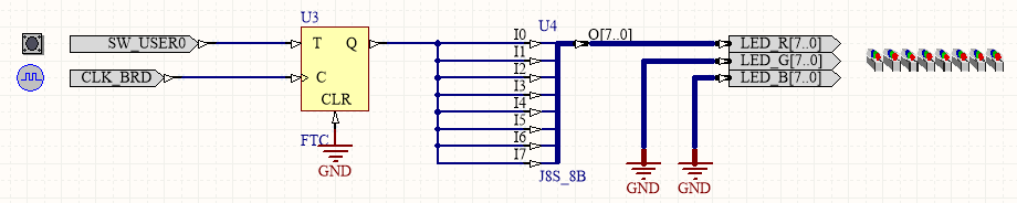
I'll briefly explain you the schematic from left to right. First there are the two inputs, the pushbutton (SW_USER0) and the board clock (CLK_BRD), needed for the Flip-Flop. Then there's the T Flip-Flop, which has its input T connected to the pushbutton, its clock input connected to the board clock, a Clear (CLR) input connected to ground as we don't needed right now, and its output Q. What you see next is a Bus Joiner. It is necessary because the board has 8 LEDs controlled by an 8-bit bus (one bit for each LED), so the single bit output from the Flip-Flop connects to each bit of the bus with this bus joiner (in this example I'll control all the 8 LEDs together). Finally the are the LEDs. The LED_G and LED_B inputs are connected to Ground because they are RGB LEDs and I only needed the RED color.
So it's done, let's try it.
It works! BAD, really bad, randomly at all. So what happened? Take a time to analyze the circuit and try to figure the problem by yourself. The solution is on the next paragraph, don't cheat!
Well, the problem is realy simple (simple to figure out once you comitted the error). The T Flip-Flop toggles its state when it has a 1 in its input, with EVERY clock pulse. The board clock is by default at 50MHz, so there's a pulse every 20ns. There's no way to push the button and release it in 20ns, so every time you push it there will be more than one pulse, even worst, an unknown number of pulses, leaving the Flip-Flop in any state but the dessired one.
The Final Solution: The D Flip-Flop
We know the problem know but... how do we solve it? The trick is that we shouldn't toggle the Flip-Flop whenever the button outputs a 1. Instead, we should only toggle the Flip-Flop only when the button was just pushed, more precisely, when the pushbutton's output changes from a 0 to a 1. To detect the transition and not just the current state of the button we need to remember the previous state, we need some memory. Memory... hmmm.. recall something?
Yes, we need another Flip-Flop. In this case we use a D Flip-Flop, d as on delay. Its behavior is really simple, it just outputs the input. How can this be useful? Because it only changes with a clock pulse, outputting the previous input, not the current, until the next pulse. So if in the previous clock pulse there was a 0 and now there's a 1 in the input, the output of the Flip-Flop will remain 0 until the next pulse, just what we needed.
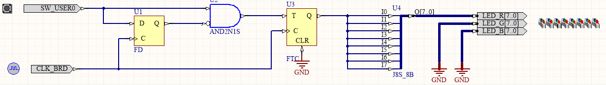
As I said earlier, we need to toggle the T Flip-Flop only if there has been a change from 0 to 1 in the pushbutton. The current state is gotten directly from the button, while the last state is obtained from the D Flip Flop. All we need is an AND gate with one input inverted, so that it only outputs a 1 when the pushbutton is 1 and the D Flip Flop is 0. The rest of the circuit remains the same, resulting in the next scheme:
The Result
A short video to show how it works
I hope you liked the tutorial, please tell me if you have any doubts or suggestions. I'll try to keep on writing posts as I learn more about FPGAs.
The project was developed using Altium Designer. You can download the files and play with them from Github